
Well Head & Xmas Tree
We are specialist in Hydraulic Workover Unit (HWU), Slick Line Unit, Hydraulic Power Pack (HPU), Rotary Table Slip Bowl, Gas Lift Valve & Mandrel.
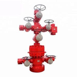
Xmas Tree
Wellhead and a Christmas tree are distinct surface components in oil and gas production, with the Wellhead or Christmas Tree acting as the foundational pressure-control base and the Christmas tree mounting on top to regulate the flow of hydrocarbons.
Api 6A Valves
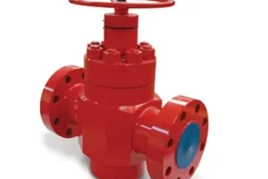
API 16A Gate Valve
API 6A valves are high-pressure control valves built to the American Petroleum Institute Specification 6A for wellheads and Christmas tree assemblies in oil and gas operations.
DSA Spool Flange
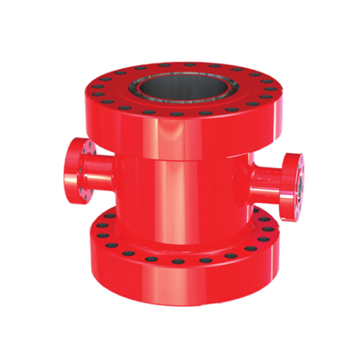
DSA Spool Flange
Double Studded Adapter (DSA) flange and a drilling/spacer spool are critical pressure-control components used in oilfield wellhead systems to connect mismatched piping or equipment.
Choke Valves & Manifold
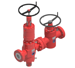
Choke Valve
A choke manifold is a high-pressure arrangement of piping and choke valves used in oil and gas operations to safely reduce wellhead pressure and control fluid flow.
API 16C Choke valves
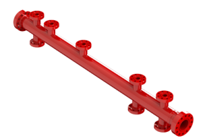
API 16C Chokes
API 16C chokes and manifolds are vital oilfield well-control devices built to American Petroleum Institute specifications. They regulate fluid flow and surface backpressure when handling kicks and maintaining bottomhole pressure.
BOP Control Unit
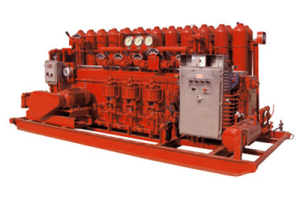
API 16D Koomey unit
An API 16D Koomey unit (also known as a BOP control unit or accumulator closing unit) is a high-pressure hydraulic power system used on oil and gas drilling rigs
What is the core difference between a Wellhead and a Christmas (Xmas) Tree assembly?
While often spoken of together, they perform independent, critical functions:
- Wellhead: The foundational, structural surface component that mechanically supports and seals casing and production tubing strings. It manages access to the well annulus during drilling and completion. [
- Christmas Tree: A series of integrated valves, chokes, and pressure-monitoring adapters installed above the tubing head once the well is completed. Its purpose is to regulate and safely isolate production flow during operations.
What is API Specification 6A?
API Specification 6A, titled “Specification for Wellhead and Christmas Tree Equipment,” is the primary industry standard published by the American Petroleum Institute (API) for the design, manufacturing, testing, and performance of wellhead and Christmas tree equipment for oil and gas drilling and production services.
- Scope: It defines requirements for materials, dimensions, testing, quality control, and marking for a wide range of equipment.
- Purpose: Its main goal is to ensure the safety, reliability, and interchangeability of equipment from different manufacturers.
- Application: It applies to equipment used for pressure containment and control in surface and subsea drilling and production operations.
Why choose CEEM FZE for Wellhead & Xmas Tree supplies?
CEEM FZE provides elite, fully engineered pressure-control packages built to thrive in harsh environments. By implementing strict Product Specification Levels (PSL 1 to PSL 4) and premium material configurations (AA to HH), CEEM FZE customizes every assembly to meet localized field pressures up to 20,000 PSI.
What makes an API 6A Gate Valve different from an API 6D Pipeline Valve?
API 6A gate valves are engineered for critical surface pressure containment and high-velocity fluid management directly at the wellhead. Unlike standard API 6D pipeline valves, API 6A valves must endure severe fluctuating downhole pressures, high concentrations of abrasive solids (like frac sand), and corrosive media (H₂S, CO₂) with extreme performance validation ratings like PR2.
What are the primary components of a surface wellhead system?
A wellhead system is a complex assembly of spools, valves, and fittings installed at the surface of a well. Its primary components are built up in stages as the well is drilled.
- Casing Head (or Starter Head): This is the lowest part of the wellhead. It attaches to the surface casing string and supports the next casing string. It provides a means of sealing the annulus between casing strings.
- Casing Spool(s): Installed on top of the casing head, these spools support and seal subsequent, smaller-diameter casing strings. A well may have multiple casing spools.
- Tubing Head (or Tubing Spool): This is the final spool installed on the wellhead. It supports the production tubing string, seals the annulus between the tubing and the final casing string, and provides access to that annulus.
- Christmas Tree: Installed on top of the tubing head, this is an assembly of valves, chokes, and fittings used to control the flow of fluids from the well during production.
Explain the API 6A Product Specification Levels (PSLs).
PSLs define different levels of technical and quality requirements for equipment. They are chosen based on the service conditions and criticality of the well. There are four main PSLs:
- PSL 1: The baseline and lowest level. It covers basic quality and testing requirements suitable for general, low-pressure service.
- PSL 2: Has more stringent requirements than PSL 1. It includes additional quality control measures, such as traceable material properties and hydrostatic testing of each unit.
- PSL 3: Designed for high-pressure, critical service. Requirements are significantly higher than PSL 2, including:
- More extensive Nondestructive Examination (NDE).
- Mandatory hydrostatic testing of each unit with longer hold times.
- More detailed material qualification and traceability.
- PSL 3G: Has all the requirements of PSL 3 plus an additional gas testing requirement. This is intended for equipment in high-pressure gas service where gas leaks are a major concern.
What are the API 6A Material Classes?
Material classes define the minimum material requirements based on the type of fluid being produced. They are based on resistance to Sulfide Stress Cracking (SSC), a form of hydrogen embrittlement caused by H₂S.
Material Classes based on NACE MR0175 / ISO 15156:
| Class | Description | Typical Application |
|---|---|---|
| AA | General Service | Non-corrosive fluids (oil, gas, water) with minimal or no H₂S. |
| BB | General Service | Similar to AA but with slightly different material property requirements. |
| CC | General Service | Similar to AA and BB. Often refers to low-alloy steels. |
| DD | Sour Service | Fluids with H₂S where the partial pressure is below 0.05 psi. Requires NACE-compliant materials with controlled hardness. |
| EE | Sour Service | Fluids with H₂S where the partial pressure is above 0.05 psi. Requires NACE-compliant materials with specific hardness and heat treatment controls. |
| FF | Sour Service | Highly corrosive applications with H₂S and high CO₂. Often requires Corrosion Resistant Alloys (CRAs). |
| HH | Sour Service | Similar to FF, for extremely corrosive environments, requiring higher-grade CRAs. |
When should a Double Studded Adapter (DSA) be utilized rather than a standard Spacer Spool?
- DSA: Perfect when space constraints exist. DSAs allow cross-over bolting between two different nominal sizes or pressure classes (e.g., transitioning from a 5,000 PSI flange to a 10,000 PSI component) using independent tap-end studs.
- Spacer/Drilling Spools: Used when distance or clearance is required between blowout preventers (BOPs) or wellhead components, often featuring side outlets for choke and kill line hookups
How does CEEM FZE ensure the integrity of its Flanges and Spools?
Every CEEM FZE DSA, drilling spool, and adapter flange is forged from premium alloy steels and precisely machined to match standard API 6B and 6BX Ring Type Joint (RTJ) configurations. For high-corrosion wells, we offer specialized Alloy 625 internal overlays inside the ring grooves to permanently prevent leakage paths.
What configurations do CEEM FZE Choke Manifolds feature?
CEEM FZE Choke and Kill Manifolds are custom-engineered, skid-mounted, pre-tested arrays. We provide configurations from 2″ to 4″ lines with operating ranges up to 15,000 PSI, outfitted with heavy-duty manual or hydraulic-actuated chokes for precise remotely monitored throttling.
What is the main operational purpose of a BOP Hydraulic Control Unit?
Also known as an accumulator system, a BOP Control Unit stores high-pressure hydraulic fluid to actuate critical drill-through equipment, including annular and ram blowout preventers. Operating under API Spec 16D standards, these units must provide safe, instant, and reliable closing pressure (typically within 30 seconds) to close off the wellbore during an unexpected influx or kick.
Why trust CEEM FZE for custom BOP Control Systems?
At CEEM FZE, safety is non-negotiable. Our BOP Control Units feature multi-pump redundancy (air and electric options), explosion-proof electrical enclosures, and ergonomic remote control panels (touchscreen or push-button) tailored for modern drilling rigs. Each system undergoes pressure testing to ensure emergency rapid response deployment in any terrain.